Solar Pump Dry Running Protection: Sensors, Controllers, and Prevention Methods
Introduction
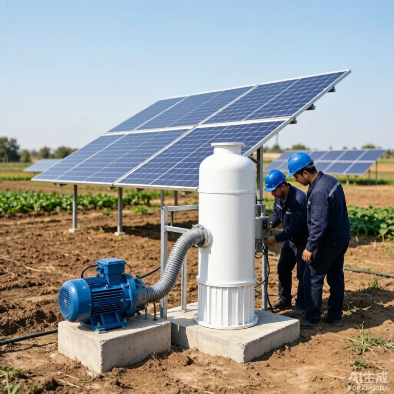
Solar water pumps operate in remote locations where maintenance access is limited, making autonomous protection mechanisms essential for long-term reliability. Dry running—when a pump operates without sufficient water flow—ranks among the most destructive failure modes, causing mechanical seal damage, motor overheating, and impeller wear that can destroy a pump within minutes. For agricultural and off-grid applications, implementing robust dry running protection is not optional but mandatory.
At KINBO, every solar pump system we manufacture integrates layered protection strategies combining hardware sensors and intelligent controllers. This guide examines the sensor technologies, controller integration methods, and installation practices that ensure your pumping system operates safely under all conditions. For foundational knowledge, review our solar water pump working principle before diving into protection specifics.
Table of Contents
Understanding Dry Running Risks in Solar Pumps
Dry running occurs when a pump operates without adequate liquid surrounding the impeller and motor assembly. In solar pumping systems, this scenario arises frequently—water source depletion, intake blockage, air locks, or rapid start-stop cycling during intermittent solar irradiance can all trigger dry running conditions.
The damage cascades through multiple pump components simultaneously:
- Mechanical Seal Damage: The mechanical seal relies on water as a lubricant and coolant. Without liquid, the seal faces rub dry, generating frictional heat exceeding 200°C within seconds. The carbon face cracks, elastomer components deform, and seal integrity fails permanently, allowing water to enter the motor chamber on the next submerged cycle.
- Motor Overheating: Submersible pump motors use surrounding water for heat dissipation. Dry running removes the cooling medium, causing winding temperatures to rise rapidly. Insulation class F (155°C) and class H (180°C) ratings can be exceeded within 5–10 minutes, degrading insulation and shortening motor life by up to 70%.
- Impeller Wear: Without water to pump, the impeller spins against air and accumulated sediment. Cavitation-like conditions develop at the eye of the impeller, eroding vane surfaces and reducing hydraulic efficiency progressively with each dry run event.
- Bearing Failure: Water-lubricated bearings in submersible pumps depend on a hydrodynamic film formed by the pumped liquid. Dry operation collapses this film, causing metal-to-metal contact that seizes bearings and generates rotor vibration that propagates to the entire motor assembly.
A single dry running incident of 60 seconds can reduce pump lifespan by an estimated 15–20%, making prevention economically critical for system operators.
Types of Dry Running Protection Sensors
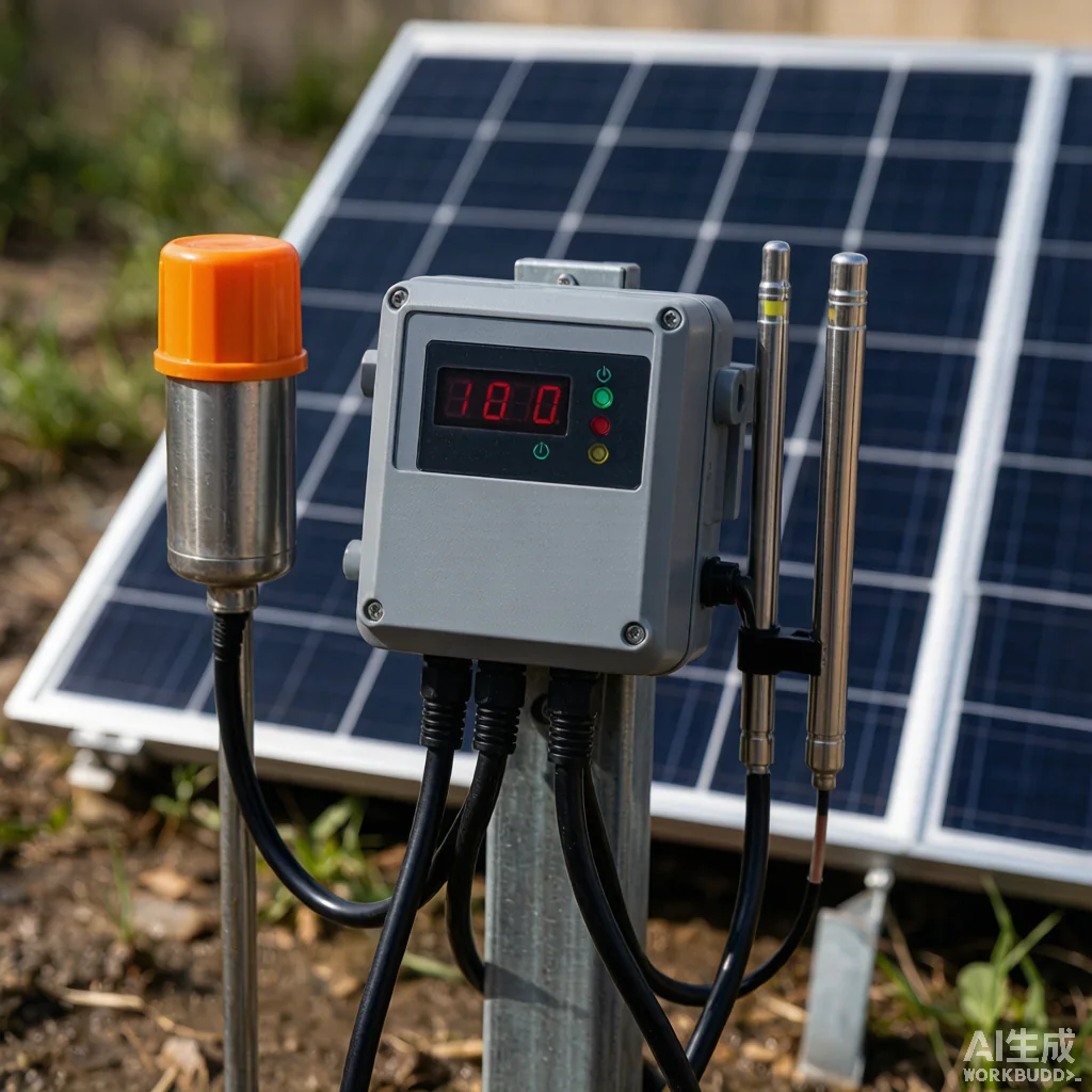
Four primary sensor technologies guard against dry running in solar pump systems. Each operates on distinct physical principles, offering trade-offs between cost, reliability, and suitability for specific installations.
Float Switches
Float switches use a buoyant element containing a mercury or reed switch that tilts as water level changes. When water drops below the threshold, the float descends and opens the circuit, signaling the controller to stop the pump. Their simplicity makes them cost-effective, though mechanical wear and fouling reduce long-term reliability.
Electrode Probes
Electrode probes detect water presence through electrical conductivity. Two or more stainless steel electrodes are mounted at different levels in the well or tank. Water bridges the electrodes, completing a low-voltage circuit. When water falls below the lower probe, conductivity drops and the controller triggers shutdown. This method offers high reliability and has no moving parts.
Pressure Switches
Pressure switches monitor discharge or suction line pressure. A drop below the preset threshold indicates the pump is moving air rather than water. These sensors respond quickly and integrate easily into existing piping but require careful calibration to avoid false triggers from normal pressure fluctuations.
Current and Voltage Monitoring
Advanced solar pump controllers monitor motor current draw and voltage patterns. Dry running changes the motor’s electrical characteristics—amperage typically drops 20–40% below normal load. The controller detects this signature and shuts down without additional sensors. This software-based approach eliminates hardware but requires precise configuration.
| Sensor Type | Detection Method | Cost Level | Reliability | Best Application |
|---|---|---|---|---|
| Float Switch | Buoyancy-triggered mechanical switch | Low | Medium | Shallow wells, storage tanks |
| Electrode Probe | Water conductivity between electrodes | Medium | High | Deep boreholes, sumps |
| Pressure Switch | Pipeline pressure threshold | Medium | High | Surface pumps, booster systems |
| Current Monitor | Motor amperage pattern analysis | Low (software-based) | High | Integrated MPPT controller systems |
KINBO solar pump controllers combine current monitoring with electrode probe inputs, providing dual-layer protection that maximizes reliability across diverse operating conditions.
Installation and Wiring Best Practices
Proper installation determines whether protection sensors function correctly throughout the pump’s service life. Follow these established practices to ensure fail-safe operation.
Sensor Placement
Position the primary water level sensor 0.5–1.0 meters above the pump intake. This distance provides a shutdown buffer, allowing the controller to stop the pump before the intake is exposed. For electrode probes, install the low-level probe at the minimum safe water depth and a high-level probe for automatic restart confirmation. Maintain a minimum 10 cm vertical separation between probes to prevent false bridging through water turbulence.
Wiring Guidelines
- Use shielded, UV-resistant cables rated for direct burial (TYPE TC-ER or equivalent) for all sensor connections exposed to sunlight.
- Separate sensor wiring from AC power cables by at least 30 cm to minimize electromagnetic interference that causes false triggers.
- Install a junction box above the maximum water level to protect splice connections from moisture ingress.
- Apply waterproof heat-shrink tubing over all sensor cable connections; standard electrical tape degrades in solar-exposed environments.
Controller Integration
Connect dry running sensor outputs to the dedicated protection input terminals on the solar pump controller. Configure the controller’s response parameters:
- Shutdown delay: Set 3–5 seconds to filter momentary sensor fluctuations caused by water surface waves.
- Restart delay: Program 5–10 minutes minimum to allow water level recovery before reattempting pump start.
- Fail-safe mode: Configure the controller to default to pump-off state if sensor signal is lost (open circuit), ensuring cable damage does not disable protection.
Wiring Verification
After installation, perform a dry test: manually lower the water level or lift the sensor and confirm the controller shuts down within the programmed delay. Document the test results and sensor positions for maintenance reference.
Troubleshooting and Maintenance of Protection Systems
Even well-installed protection systems require periodic inspection. The following troubleshooting guide addresses the most common field issues encountered with solar pump dry running protection.
False Trigger Shutdowns
If the pump shuts down despite adequate water levels, inspect for these causes:
- Electrode fouling: Mineral scale or biological growth on probe surfaces increases contact resistance, mimicking dry conditions. Clean electrodes with a non-abrasive brush and mild acid solution every 3–6 months in hard water areas.
- Float switch entanglement: Debris or cable tangles can prevent the float from rising. Ensure the float moves freely and install a guide tube if the well has significant particulate content.
- Electrical noise: Nearby inverters or radio transmitters can induce signals in unshielded sensor cables. Verify shield grounding and install ferrite cores at sensor terminals if interference persists.
Sensor Failure to Trigger
When the pump continues running in dry conditions, the protection system may have failed. Test the sensor circuit by simulating a dry condition and measuring controller input voltage. A functioning sensor should toggle the input between logic states (0V to 5V or 12V). If no change occurs, replace the sensor and inspect wiring continuity.
Periodic Testing Procedure
Establish a quarterly testing protocol:
- Visually inspect all sensor cables for abrasion, UV damage, or water ingress at junction boxes.
- Perform a manual dry simulation test and verify controller response time matches configured delays.
- Clean electrode probes and float switch mechanisms per manufacturer specifications.
- Record test results, sensor positions, and any parameter adjustments in the system maintenance log.
For comprehensive pump care beyond protection systems, consult our solar pump maintenance guide for scheduled service intervals and component inspection procedures.
Frequently Asked Questions
Q1: Can a solar pump recover automatically after a dry running shutdown?
Yes, when equipped with an automatic restart controller. After the programmed delay (typically 5–10 minutes), the controller checks the water level sensor. If water has recovered above the restart threshold, the pump resumes operation. However, if dry conditions persist, the controller remains in shutdown mode to prevent damage. KINBO controllers feature configurable auto-restart with configurable retry limits to prevent excessive cycling.
Q2: What is the maximum response time for effective dry running protection?
The protection system should trigger shutdown within 5 seconds of water loss detection. Mechanical seals begin sustaining damage after approximately 30 seconds of dry operation, while motor winding insulation degrades measurably after 60 seconds. A properly configured sensor-controller combination achieves sub-3-second response, providing ample safety margin.
Q3: Is current monitoring sufficient without a physical water level sensor?
Current monitoring provides reliable secondary protection but should not be the sole method in critical applications. Motor current signatures can vary with voltage fluctuations, particularly in solar systems during cloud cover transitions. For mission-critical installations, combine current monitoring with at least one physical sensor (electrode probe or float switch) for redundant protection. This layered approach ensures coverage if either system fails independently.
Protect Your Pumping Investment with KINBO
Every KINBO solar pump is engineered with integrated dry running protection and intelligent controller logic. Need technical support, spare sensors, or controller configuration assistance?
August 12, 2026 | Author: KINBO Editorial Team