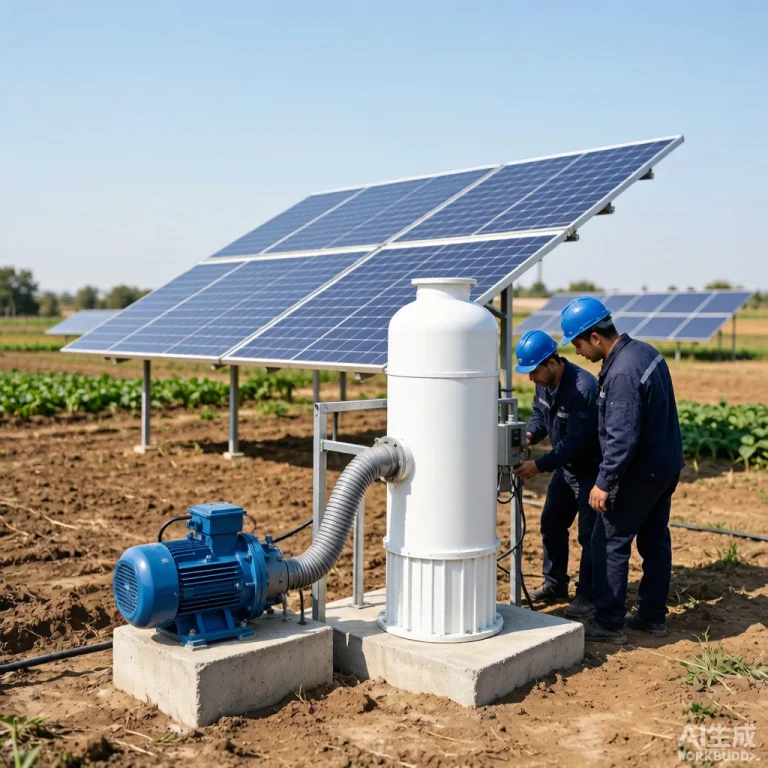
Solar Pump Harmonic Distortion, EMI, and Electrical Noise Mitigation: A Field Guide for Engineers
Introduction
Modern solar water pump systems rely on variable frequency drives (VFDs), MPPT controllers, and switched-mode power electronics to convert DC solar power into the precise AC output a pump motor needs. While these devices deliver outstanding efficiency, they also introduce harmonic distortion, electromagnetic interference (EMI), and conducted electrical noise that can damage bearings, trip grid protection, and corrupt sensor signals. For commercial and agricultural projects, ignoring power quality can lead to premature motor failure, higher maintenance costs, and rejected equipment certifications. Manufacturers such as KINBO design solar pump controllers with harmonic-aware firmware and EMC-tested hardware to help project owners meet grid codes in Africa, Southeast Asia, the Middle East, and Latin America.
Table of Contents
Understanding Harmonic Distortion in Solar Pump Systems
Harmonic distortion occurs when the sinusoidal current waveform is no longer a pure 50 Hz or 60 Hz sine wave. Power-electronic switches inside a solar pump inverter draw current in short pulses, creating integer multiples of the fundamental frequency called harmonics. In large solar pump arrays, these harmonics circulate through cables, transformers, and adjacent equipment, causing overheating and measurement errors.
Why Variable Frequency Drives Create Harmonics
VFDs use pulse-width modulation (PWM) to vary motor speed. The rapid switching edges contain high-frequency energy that appears as both harmonic currents on the supply side and bearing currents inside the motor. Submersible motors are especially vulnerable because long motor cables act as antennas, radiating high-frequency noise into the surrounding soil and water.
Sources of EMI and Electrical Noise
EMI in a solar pumping system is rarely caused by a single device. Instead, it results from the interaction of the PV array, DC cabling, inverter switching, motor cabling, and earthing layout. Common noise sources include:
- PWM switching edges from the VFD output stage, typically 2–16 kHz.
- DC-side ripple produced by the MPPT converter when tracking maximum power point under rapidly changing irradiance.
- Arcing contacts in relays, contactors, or loose terminal blocks on long cable runs.
- Grid-tied export inverters that inject high-frequency noise back into a weak rural distribution network.
Conducted noise travels along power conductors, while radiated noise affects nearby communication cables, level sensors, and telemetry radios used for remote monitoring.
Measurement and Standards for Harmonic Emissions
Power-quality measurement is the first step before applying any mitigation. Engineers typically record voltage THD, current THD, and individual harmonic orders up to the 50th using a power analyzer at the point of common coupling. International standards provide acceptance thresholds for different system sizes and grid types.
| Standard / Parameter | Typical Limit | Application Scope |
|---|---|---|
| IEC 61000-3-6 (Voltage THD) | ≤ 8 % | Medium-voltage public distribution |
| IEC 61000-3-12 (Current THD) | ≤ 22 % for 16–75 A systems | Low-voltage installations |
| IEEE 519 (Current TDD) | 5–20 % depending on ISC/IL | North American utility interconnection |
| Motor bearing voltage | < 10 % of DC bus voltage | Shaft-voltage mitigation targets |
Note: Exact limits depend on local grid codes, short-circuit ratio, and installed capacity. Always verify the latest revision of the applicable standard for the target country.
Mitigation Techniques: Filters, Shielding, and Grounding
Once the harmonic signature is known, engineers can select a mitigation strategy that balances cost, efficiency, and reliability. The most common methods include passive harmonic filters, active harmonic filters, shielded motor cables, and shaft grounding devices.
| Mitigation Method | Best For | Typical Result |
|---|---|---|
| AC line reactor / DC choke | Low-cost current THD reduction | 3–8 % THD improvement |
| Passive tuned harmonic filter | Fixed dominant 5th/7th harmonics | 15–25 % THD reduction |
| Active harmonic filter (AHF) | Variable loads, mixed loads | < 5 % current THD achievable |
| Shielded motor cable + ferrite | Bearing current mitigation | Reduces dV/dt and radiated EMI |
| Common-mode choke | Conducted EMI on DC bus | 10–20 dB noise reduction |
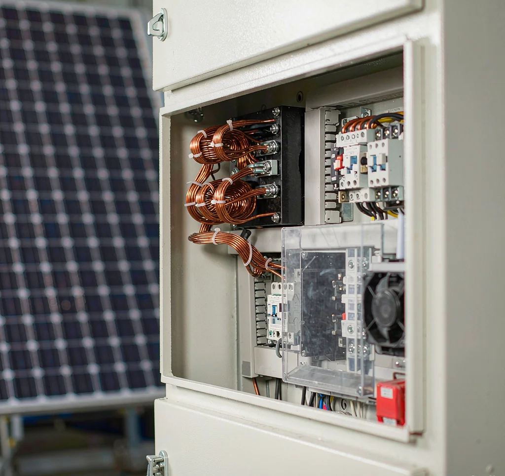
KINBO solar pump controllers are factory-tested with shielded cables and optional DC chokes, allowing system integrators to pass EMC site acceptance tests without expensive retrofits. Selecting a controller with integrated common-mode filtering is often more cost-effective than adding external filters later.
System Design Checklist for Clean Power
A clean-power design starts at the BOM stage. Project engineers should review the following items before commissioning:
- Specify a VFD carrier frequency that balances acoustic noise and harmonic content; lower frequencies reduce switching losses but increase audible motor whine.
- Keep DC cable runs short between the PV array and inverter to minimize stray inductance and DC-side oscillations.
- Use continuous shielded motor cable with 360-degree termination at both the inverter and motor junction boxes.
- Install a single-point ground reference for all enclosures, cable shields, and surge arresters to prevent ground loops.
- Record baseline power-quality data at commissioning and again after 90 days of operation to detect degradation.
- Leave space and mounting provisions for harmonic filters or active filters if future grid-code updates require lower emissions.
Frequently Asked Questions
What is total harmonic distortion (THD) in a solar pump system?
THD is the ratio of the combined RMS value of all harmonic frequencies to the RMS value of the fundamental 50 Hz or 60 Hz component. High THD indicates a distorted waveform that can overheat transformers, trip protective relays, and shorten motor life.
Can harmonic distortion damage a submersible pump motor?
Yes. PWM voltage pulses from the inverter create shaft voltages that discharge through motor bearings, causing electrical pitting (fluting), increased vibration, and premature bearing failure. Shielded cables and shaft grounding devices reduce this risk.
Are harmonic filters mandatory for every solar pump installation?
No. Filters are typically required only when local grid codes, utility interconnection agreements, or sensitive neighboring loads demand compliance with specific harmonic limits. Many small off-grid solar pump systems operate without filters.
How can I measure EMI on a remote solar pump site?
Use a handheld power-quality analyzer for conducted harmonics, and a near-field probe or spectrum analyzer for radiated emissions from cables and enclosures. For long-term monitoring, select a telemetry unit with EMC-hardened inputs and shielded sensor wiring.
Conclusion
Harmonic distortion, EMI, and electrical noise are manageable engineering challenges when they are addressed during the design phase rather than after installation. By selecting EMC-tested solar pump controllers, applying proper filtering and shielding, and following international power-quality standards, project owners can protect motors, satisfy grid codes, and reduce lifetime maintenance costs. A clean-power solar pumping system is not only more reliable but also easier to warranty and finance across global markets.
For B2B buyers specifying clean-power solar pumping equipment, contact KINBO for competitive FOB pricing and harmonic-mitigation engineering support.