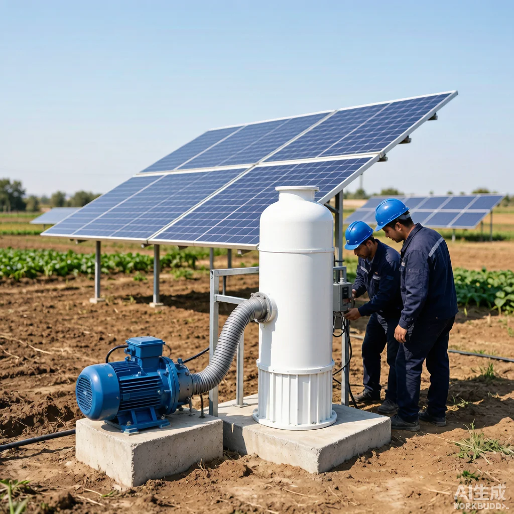
Solar Pump Factory Acceptance Testing and Quality Inspection Protocols
Introduction
When procuring solar water pumps for agricultural, municipal, or industrial applications, the factory acceptance test (FAT) is the single most critical gatekeeper between specification promises and operational reality. A pump that underperforms by 15% on hydraulic efficiency translates directly into oversized solar arrays, unnecessary capital expenditure, and compromised system reliability over a 20-year service life. For professional buyers sourcing from overseas manufacturers, understanding FAT protocols is not optional — it is the foundation of supply chain quality assurance. KINBO, as a manufacturer of solar pumping systems with thousands of installations across 40+ countries, has refined its FAT procedures to align with international benchmarks including ISO 9906 Grade 1 testing, IEC 60034 motor standards, and NEMA MG-1 for insulation systems. This article provides a technically grounded, actionable framework for buyers and quality engineers to evaluate solar pump factory testing — what to request, what to inspect, and how to interpret results before a single unit leaves the production floor.
Table of Contents
Factory Acceptance Test (FAT) Standards and Procedures
FAT for solar centrifugal and submersible pumps is governed primarily by ISO 9906:2012 Rotodynamic Pumps — Hydraulic Performance Acceptance Tests, which defines three test grades with progressively tighter tolerance bands. Grade 1 (highest precision) applies a flow rate tolerance of ±4.5%, head tolerance of ±3%, and pump efficiency tolerance of ±3% — parameters that differentiate high-quality manufacturers from commodity producers. Grade 2 loosens these to ±6%, ±4%, and ±4% respectively, while Grade 3 (used only for very large or field-installed units) extends to ±9% flow and ±5.5% head tolerances. For solar pump procurement, buyers should insist on Grade 1 or Grade 2 testing as a contractual requirement, documented in the Inspection and Test Plan (ITP) before production begins.
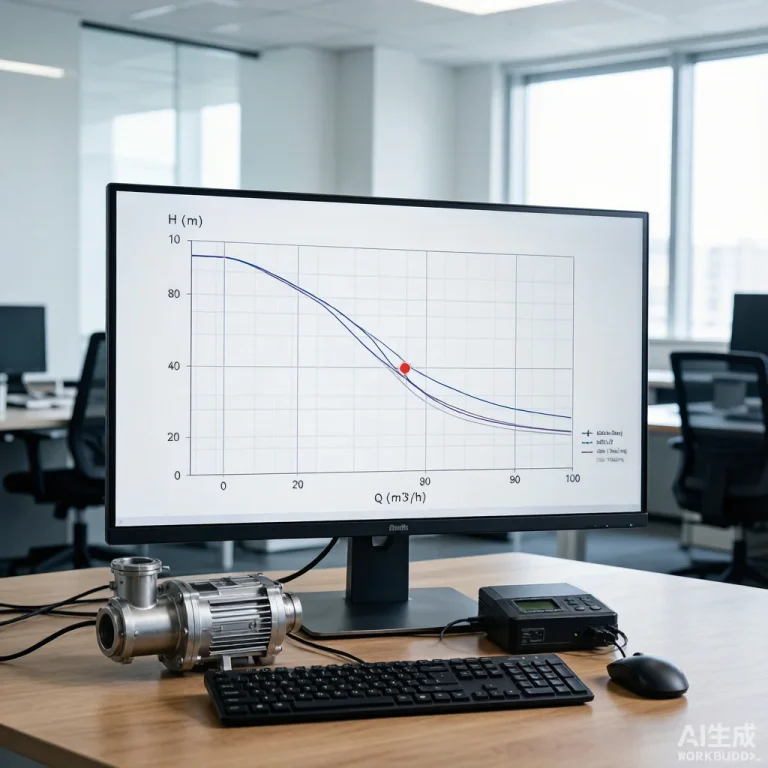
The hydraulic performance test itself operates on a closed-loop test bench with calibrated instrumentation: electromagnetic flowmeters with ±0.2% accuracy, precision pressure transducers at suction and discharge, and a variable-frequency drive (VFD) simulator that replicates the actual solar array’s IV curve rather than a flat DC power supply. This distinction is critical — a pump tested on a laboratory DC supply at constant voltage will produce inflated performance curves compared to real solar conditions where voltage sags under cloud cover and irradiance variations. KINBO conducts FAT runs at five operating points along the pump curve: shut-off (zero flow), minimum continuous stable flow, best efficiency point (BEP), 110% of BEP flow, and maximum allowable flow. At each point, flow, total dynamic head, power input, pump efficiency, and NPSH margin are recorded and plotted against the guaranteed performance envelope. A minimum runtime of 30 minutes at BEP is standard; vibration readings per ISO 10816-7 (Class II limits typically below 2.8 mm/s RMS for pumps under 15 kW) are taken simultaneously. Any deviation exceeding the agreed tolerance band triggers a root-cause analysis and corrective action before shipment authorization.
Key Quality Inspection Checkpoints
Before hydraulic testing begins, a structured incoming and in-process quality inspection sequence establishes that every component meets design specifications. The inspection regime should be defined in an ITP aligned with ISO 9001:2015 quality management requirements and documented with hold points, witness points, and review points that both the manufacturer and buyer agree upon in writing.
| Checkpoint | Inspection Method | Acceptance Criteria | Stage |
|---|---|---|---|
| Material Certification (Impeller, Diffuser, Shaft) | Mill Test Certificate (MTC) per EN 10204 Type 3.1; PMI verification via handheld XRF for stainless steel grades (304, 316, duplex 2205) | Chemical composition within ASTM/EN grade tolerance; Cr ≥ 16.0% for 304 SS, Mo ≥ 2.0% for 316 SS | Incoming |
| Casting Integrity (Impeller, Volute, Diffuser) | Visual inspection per MSS SP-55; dye penetrant (PT) for surface defects; radiographic testing (RT) for critical class castings | No cracks, porosity >2mm, shrinkage cavities, cold shuts; surface roughness Ra ≤ 6.3μm for hydraulic passages | Incoming |
| Dimensional Inspection | CMM (Coordinate Measuring Machine) for impeller vane profiles, wear ring clearances, shaft runout | Wear ring clearance within design tolerance ±0.05mm; shaft TIR ≤ 0.03mm per ISO 1940 G6.3 balance grade | In-Process |
| Hydrostatic Pressure Test | Pump casing pressurized to 1.5× maximum allowable working pressure (MAWP) for minimum 30 minutes | Zero visible leakage; pressure drop ≤ 2% over test duration; no permanent deformation | In-Process |
| Dynamic Balance (Rotor Assembly) | Two-plane dynamic balancing machine per ISO 21940-11 | Residual unbalance ≤ G6.3 grade (6.3 mm/s); for pumps > 3000 RPM, G2.5 is recommended | Pre-Assembly |
Material traceability is particularly important for solar pumps destined for corrosive groundwater (pH < 6 or > 9, chloride > 250 mg/L, TDS > 2 000 mg/L). In such cases, 316 stainless steel or duplex 2205 material certification becomes mandatory, and the ITP should require positive material identification (PMI) on 100% of pressure-containing and wetted components. For deep-well submersible pumps, the column pipe and coupling material certificates should be cross-checked against the tensile strength and yield strength specified in the mechanical design calculation — a coupling that fails at 80% of rated load due to substandard material can cause a complete pump string loss in a borehole, with recovery costs exceeding the pump’s purchase price several times over.
Electrical and Insulation Testing During FAT
The motor — whether a permanent magnet synchronous motor (PMSM), brushless DC (BLDC), or asynchronous AC induction type — is the heart of a solar pumping system, and its electrical integrity testing during FAT is non-negotiable. The test sequence follows IEC 60034-1 (Rotating Electrical Machines — Rating and Performance) and typically comprises four mandatory evaluations.
Insulation Resistance (IR) Test: Conducted with a megohmmeter (megger) at 500V DC for motors rated below 600V, or 1000V DC for motors rated 600-1000V. The IR value is measured at 1 minute and corrected to 40°C reference temperature per IEEE 43. The minimum acceptable IR for a new winding is 100 MΩ; values below 5 MΩ are a hard reject. The polarization index (PI = R10min / R1min) should exceed 2.0 for Class F or H insulation systems, indicating the insulation is free of moisture and contamination. For submersible motors, the test should be performed both before and after the motor is filled with the water-glycol fill solution to detect any fill-fluid quality issues.
Winding Resistance Measurement: Each phase winding is measured using a four-wire Kelvin bridge micro-ohmmeter with resolution to 0.001 Ω. Phase-to-phase resistance imbalance must not exceed 2% of the average; imbalance above this threshold indicates a manufacturing defect in the winding process (wrong turn count, poor crimp joint, or damaged conductor insulation during insertion). Temperature is recorded simultaneously to normalize readings to 20°C.
High-Potential (HiPot) Dielectric Withstand Test: Per IEC 60034-1, the test voltage is applied between windings and frame at (2 × rated voltage + 1000V) for 60 seconds, with a minimum of 1500V AC. For a 380V motor, this means a test voltage of 1760V. The test is passed if no breakdown or flashover occurs. Some specifications also require a surge comparison test that applies a fast-rising impulse to detect turn-to-turn insulation weaknesses that the HiPot may miss.
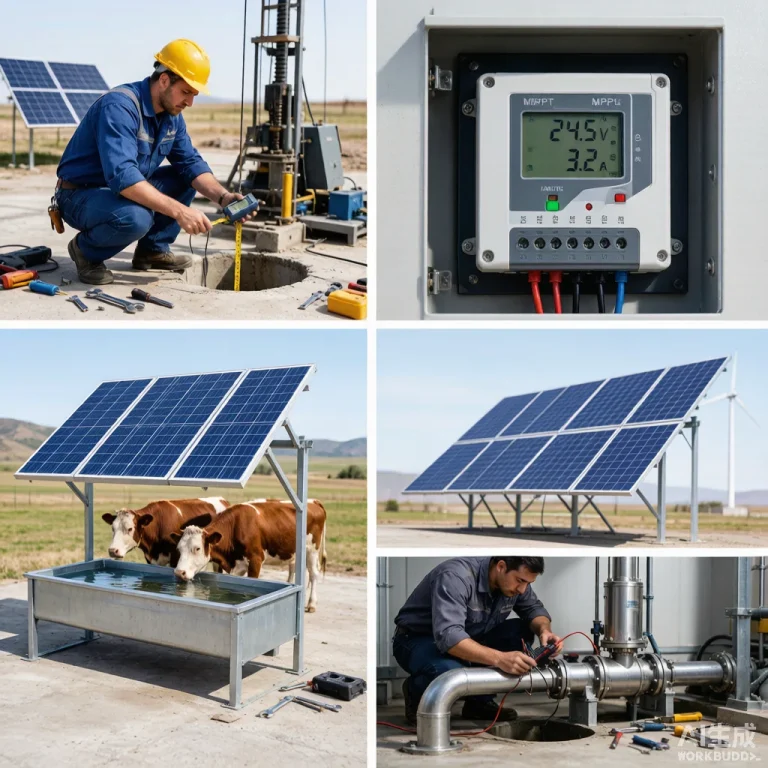
No-Load Run Test: The motor is run uncoupled at rated voltage and frequency (or simulated via VFD) for a minimum of 30 minutes. No-load current, voltage balance, and bearing temperatures (measured by embedded RTD or infrared) are logged every 5 minutes. Bearing temperature rise should not exceed 40 K above ambient for grease-lubricated bearings, and vibration measured on the bearing housings should remain within ISO 10816-3 Zone A (newly commissioned machine) limits. For solar pump controllers (MPPT-based inverters), an additional functional test verifies MPPT tracking accuracy (±1% of maximum power point), dry-run protection activation at <0.5m water level (or pre-set low current threshold), and automatic restart sequencing.
How to Audit a Solar Pump Factory
A factory audit goes beyond the product-level FAT to evaluate whether the manufacturer’s quality management system, production processes, and technical capabilities can sustain consistent quality across batch production. Buyers should approach the audit with a structured checklist covering at minimum six dimensions.
Production Equipment and Calibration: Verify that the hydraulic test bench itself holds valid calibration certificates (ISO 17025-accredited lab) for flowmeters, pressure transducers, power analyzers, and torque sensors — calibration intervals should not exceed 12 months. The test bench must be capable of operating across the full range of the pumps being procured; a bench rated for 10 m³/h cannot accurately test a pump delivering 50 m³/h. Confirm that static balancing machines, CMM equipment, and winding machines are all maintained on a documented preventive maintenance schedule.
Incoming Material Control: Review the receiving inspection records for a sample of production lots — do the records match the material certificates? Are non-conforming materials segregated in a clearly marked quarantine area with defined disposition procedures (return to vendor, use-as-is with concession, scrap)? The presence of an organized material control process with first-in-first-out (FIFO) inventory management and climate-controlled storage for motor winding wire and insulation materials is a strong positive indicator.
Process Control and Traceability: Walk the production line and observe whether each pump assembly carries a unique serial number or traveler document that links back to: (a) the batch numbers of all major components, (b) the date and operator for each assembly station, (c) the in-process inspection results at hold points. Electronic traceability via barcode or RFID is preferred, but a disciplined paper-based traveler system is acceptable. Ask to trace one completed pump back to its raw material certifications — a capable factory can complete this trace within 30 minutes.
Non-Conformance and Corrective Action: Request to see the corrective action log for the last 12 months. Look for evidence of root cause analysis (5-Why, fishbone diagram, or 8D reports), verified corrective actions with measurable effectiveness criteria, and closure within defined timelines. A factory that cannot produce documented corrective actions for recurring FAT failures — seal leakage, vibration exceedances, or winding burnout during HiPot — is a high-risk supplier regardless of how well a single demonstration unit performs.
Workforce Competency: Operators performing NDT (dye penetrant, ultrasonic, radiographic) should hold Level II certification per ISO 9712 or ASNT SNT-TC-1A. Welders on pressure-containing components should be qualified to ASME Section IX or ISO 9606-1. Motor winding technicians should demonstrate consistent winding tension control and slot fill factor awareness — sloppy winding work is a leading cause of premature motor failure in submersible solar pumps.
Witness Testing Protocol: For high-value orders, buyers should designate witness points in the ITP and either attend FAT in person or engage a third-party inspection agency (SGS, Bureau Veritas, TÜV, Intertek). The witness should verify that (a) test instruments are within calibration, (b) the test procedure follows the approved ITP without shortcuts, (c) test data is recorded in real time — not transcribed from handwritten notes after the fact, and (d) any test failures are documented with a non-conformance report and re-tested after corrective action. KINBO welcomes third-party inspector attendance at FAT and provides advance notification of test schedules to facilitate buyer or inspector coordination.
Frequently Asked Questions
Q: What tests should a buyer request during factory acceptance?
A: At minimum, the FAT scope should include: (1) hydraulic performance testing at 5 operating points per ISO 9906 Grade 1 or Grade 2 on a solar-simulated power supply (not a flat DC bench supply); (2) insulation resistance and polarization index testing per IEEE 43, plus HiPot dielectric withstand testing per IEC 60034-1; (3) hydrostatic pressure test at 1.5× MAWP for the pump casing; (4) motor no-load run test with vibration per ISO 10816 and bearing temperature monitoring; (5) MPPT controller functional test including dry-run protection activation, soft-start sequencing, and automatic restart behavior; (6) dimensional verification of critical fits (wear ring clearances, impeller-to-volute gap, shaft runout); and (7) material certification review with PMI spot-checking for stainless steel components. For submersible pumps, add a submerged run test at rated depth simulation to verify thrust bearing load capacity and motor fill-fluid integrity. All test data should be compiled into a formal FAT report signed by both the manufacturer’s quality manager and the buyer’s representative before shipment release.
Q: Can third-party inspectors perform FAT, and is this common in the solar pump industry?
A: Yes, third-party inspection (TPI) during FAT is standard practice for larger procurement programs and is strongly recommended for first-time buyers or orders exceeding USD 50,000. Agencies such as SGS, Bureau Veritas, TÜV Rheinland, and Intertek offer pump FAT witness services globally, including in major solar pump manufacturing regions. The TPI scope should be defined in the ITP as “Witness” hold points for hydraulic testing and “Review” for material certification. Costs typically range from USD 800 to USD 2,500 per inspection day depending on the region and inspector qualifications, plus travel expenses. Most established solar pump manufacturers — including KINBO — routinely accommodate TPI attendance and provide advance test schedule notifications. The buyer should supply the TPI agency with the purchase order technical specification, approved ITP, and applicable acceptance standards before the inspection to avoid disputes on-site. For remote buyers who cannot attend in person, a hybrid approach combining TPI witness testing with real-time video streaming of test instrumentation displays is increasingly common and cost-effective.
Q: How do factory test results correlate with actual field performance?
A: Factory test results under controlled laboratory conditions typically represent the best-case performance baseline. In the field, several degradation factors apply: (1) solar irradiance variability — a pump certified at 1 000 W/m² solar input may operate at 600-900 W/m² for much of the day, reducing flow proportionally; (2) actual well drawdown and dynamic water level fluctuations that differ from the fixed test head; (3) pipe friction losses that are calculated but not physically present during FAT — an additional 5-15% head loss in long discharge pipelines can shift the operating point away from BEP; (4) water quality differences — abrasive sand content above 50 g/m³ accelerates wear ring and impeller erosion, reducing efficiency by 3-8% within the first 1 000 operating hours; (5) ambient temperature extremes — motor winding resistance increases approximately 0.4% per °C above rated temperature, reducing motor efficiency. A well-correlated FAT-to-field performance expectation would be: field flow within 90-95% of FAT-certified flow at the same total dynamic head, assuming clean water and design solar conditions. Greater deviation usually indicates installation issues (incorrect pipe sizing, undersized cables causing voltage drop, or array orientation errors) rather than pump quality problems. This is why post-installation commissioning testing — measuring actual flow, head, power, and system efficiency — is as important as FAT for verifying the installed system meets design intent.
Ensure your next solar pump procurement includes a rigorous factory acceptance testing protocol — contact KINBO to discuss customized FAT procedures and third-party inspection coordination for your project requirements.