Solar Pump Float Switch and Level Control Systems
Introduction
Float switches and level control systems are the unsung guardians of solar pump installations—inexpensive components that prevent the most expensive failure mode: a pump running dry. A $30 float switch protecting a $2,500 pump represents the highest-ROI investment in any solar pumping system. For B2B procurement professionals and system integrators, understanding the range of level control options—from simple mechanical floats to ultrasonic sensors with remote monitoring—enables specification of protection systems matched to site criticality and budget. KINBO solar pump controllers accept multiple level sensor input types, providing flexible integration with the full spectrum of level control technologies.
Table of Contents
Float Switch Types and Technologies
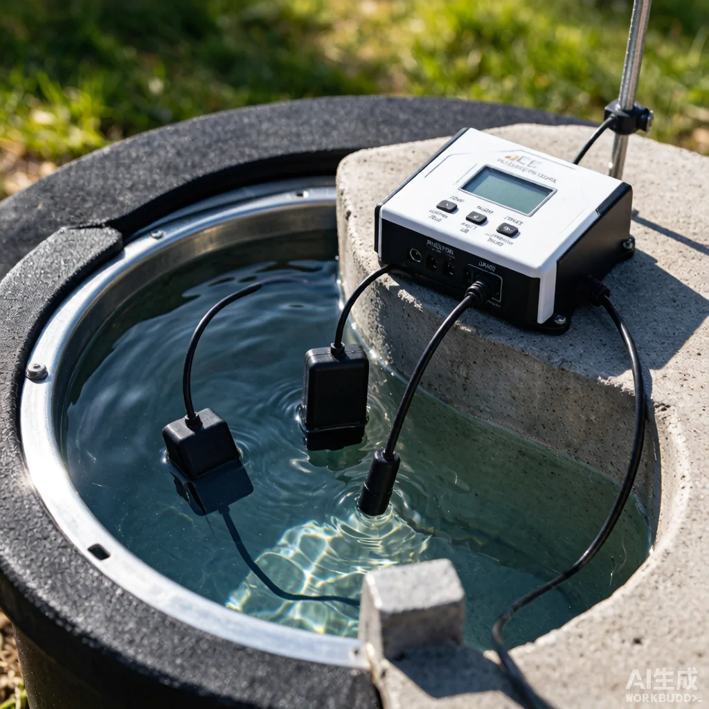
Three float switch technologies dominate solar pump applications, each suited to different operating environments. Mechanical mercury float switches use a glass vial containing mercury that makes or breaks contact as the float tilts with water level changes. They are the most reliable option for basic high/low level detection, with a typical service life exceeding 100,000 cycles (15-20 years in normal use). However, mercury switches are being phased out in many jurisdictions under environmental regulations restricting mercury use.
Mechanical microswitch floats replace mercury with a steel ball that actuates a microswitch as the float tilts. They offer equivalent functionality without mercury, but the microswitch contacts are more susceptible to corrosion in humid wellhead environments. Sealed units with epoxy-potted switches mitigate this vulnerability. Conductivity probe sensors use two or more stainless steel electrodes at different depths. When water bridges both electrodes, a low-voltage circuit is completed, signaling the controller. Conductivity probes have no moving parts and are immune to mechanical failure, but they cannot distinguish between clean water and conductive contaminants, and electrode fouling in hard water requires periodic cleaning.
Installation and Wiring Best Practices
Float switch installation must account for three critical levels: the pump stop level (lowest water level at which the pump shuts off, typically 2-3 meters above the pump intake), the pump start level (water level at which the pump is allowed to restart, typically 1-2 meters above the stop level to prevent short-cycling), and the high-level alarm (overflow prevention for tank-fill applications). The hysteresis between start and stop levels prevents rapid on/off cycling that would damage the pump and controller.
Float switch cable should be secured to the drop pipe at 2-meter intervals using stainless steel cable ties—never electrical tape, which degrades and releases the cable within months. The cable must have sufficient slack to accommodate water level fluctuations without tension on the switch. For deep-well installations where the float switch cable length exceeds 50 meters, use a weighted cable guide tube (PVC pipe attached to the drop pipe) to prevent the float cable from tangling with the pump cable or safety rope during installation and retrieval.
Level Control Technology Comparison
| Technology | Moving Parts | Cost | Lifespan | Best Application |
|---|---|---|---|---|
| Mechanical Float (Mercury) | Yes (tilting) | $25-50 | 15-20 years | Shallow wells, storage tanks |
| Mechanical Float (Microswitch) | Yes (tilting) | $30-60 | 10-15 years | Mercury-free replacement |
| Conductivity Probe | None | $40-80 | 8-12 years | Deep wells, clean water |
| Pressure Transducer | None | $200-500 | 8-12 years | Continuous monitoring, large systems |
| Ultrasonic Sensor | None | $150-300 | 10-15 years | Tanks, non-contact required |
Note: Costs are for sensor only, excluding controller interface modules if required.
Automation and Remote Monitoring
Modern solar pump controllers can use float switch inputs not just for pump protection but for automated system control. A dual-float configuration in a storage tank enables automatic pump start when water drops below the lower float and automatic stop when the tank refills to the upper float—effectively creating a fully autonomous water supply system that requires no human intervention between scheduled maintenance visits. When combined with GSM-based remote monitoring, the controller can transmit tank level data and pump status to a cloud dashboard, alerting operators via SMS if water level approaches the critical low threshold or if the pump fails to start within the expected window after the low-float trigger.
For multi-pump installations serving a common storage tank, float switches can provide cascade control: the first pump starts at 50% tank level, the second at 30%, and both stop at 90%. This staged operation maximizes the use of solar energy by running fewer pumps during low-demand periods and scales up automatically during peak usage. See our well water level monitoring guide for integrated sensor-controller design strategies.
Frequently Asked Questions
Q: How many float switches does a typical solar pump system need?
A: Minimum two: one low-level switch in the well to prevent dry running, and one high-level switch in the storage tank to prevent overflow. For automated operation, add a second float in the tank for pump start control. Systems with remote monitoring or cascade pump control may use 3-5 floats.
Q: Can I add a float switch to an existing installation without pulling the pump?
A: Yes, for surface-level applications (storage tank level control) and for wellhead-mounted ultrasonic sensors. A downhole float switch installed in the well casing requires pulling the pump to attach the switch to the drop pipe at the correct depth relative to the pump intake.
Q: How do I prevent float switch cables from tangling during pump installation?
A: Use a cable guide tube (PVC pipe strapped to the drop pipe) to contain the float cable. Secure all cables at 2-meter intervals with stainless steel ties. Never use electrical tape or plastic zip ties for downhole cable management—they degrade and release within months, creating a tangle hazard during pump retrieval.
For B2B system integrators requiring float switch and level control solutions, contact KINBO for compatible sensor specifications and controller integration support.
Related Articles
- Well Water Level Monitoring Guide
- Controller Protection Features
- Explore KINBO Solar Submersible Pumps