Solar Pump Water Hammer Protection and Surge Control Methods for Long Pipelines
Introduction
Water hammer is one of the most destructive hydraulic phenomena encountered in solar water pumping systems—particularly those with long-distance pipelines. When a column of water is suddenly halted by a rapid valve closure or pump shutdown, the kinetic energy converts into a high-pressure shockwave that travels back through the pipeline at speeds exceeding 1,200 meters per second. This pressure surge can rupture pipes, destroy pump impellers, and cause catastrophic system failure within milliseconds.
For B2B buyers and project engineers specifying solar pumping solutions for agricultural irrigation, community water supply, or industrial transfer applications, understanding water hammer protection is not optional—it is a fundamental design requirement. A well-engineered surge protection strategy extends equipment lifespan, reduces maintenance downtime, and safeguards the return on investment. KINBO, as a specialized solar water pump manufacturer, integrates surge-mitigation design principles into every system recommendation—from component selection through complete installation guidance. For a deeper understanding of how solar pumps operate under varying hydraulic conditions, see our solar water pump working principle guide.
Table of Contents
What Is Water Hammer in Solar Pump Systems
Water hammer, also known as hydraulic shock or pressure surge, is a transient pressure wave generated when a fluid in motion is forced to stop or change direction abruptly. In a solar water pumping system, this typically occurs when a pump starts or stops, or when a downstream valve closes faster than the water column can decelerate. The kinetic energy of the moving water mass is instantaneously converted into pressure energy, creating a shockwave that propagates through the entire pipeline network.
The physics behind water hammer was first described by the Joukowsky equation: ΔP = ρ × c × ΔV, where ΔP is the pressure rise, ρ is fluid density, c is the wave speed (speed of sound in the fluid-pipe system), and ΔV is the change in flow velocity. For a typical PVC pipeline carrying water at 2 m/s, a sudden pump stop can generate a pressure surge of 20–30 bar (290–435 psi)—well beyond the pressure rating of standard piping and pump components.
In solar-powered systems, the risk is amplified by the intermittent nature of solar energy. Cloud passages cause irradiance fluctuations that lead to repeated pump cycling, while daily startup and shutdown sequences subject the pipeline to frequent transient events. Without adequate protection, cumulative fatigue damage accelerates component degradation and ultimately leads to premature failure.
Causes and Risk Factors in Solar Pumping Pipelines
Multiple operational and design factors contribute to water hammer risk in solar pumping installations. Understanding these root causes enables engineers to implement targeted mitigation strategies during the design phase rather than addressing failures reactively.
- Rapid Valve Closure: Spring-loaded check valves or fast-acting solenoid valves can close in under 0.5 seconds, creating a near-instantaneous flow stoppage. The shorter the closure time relative to the pipeline’s wave reflection period (2L/c), the more severe the pressure surge.
- Pump Start and Stop Events: Direct-on-line (DOL) pump starts generate initial torque surges that translate into hydraulic transients. Uncontrolled pump shutdown—particularly during power loss or low-irradiance conditions—allows the water column to reverse direction and slam into the check valve.
- Long Pipeline Lengths: The magnitude of water hammer is directly proportional to pipeline length. A 500-meter pipeline contains a much larger mass of moving water than a 50-meter run, storing significantly more kinetic energy that must be dissipated during transient events.
- High Flow Velocities: Design guidelines typically recommend flow velocities between 0.6 and 1.5 m/s for suction lines and 1.5 to 2.5 m/s for discharge lines. Exceeding these velocities—common when engineers undersize pipe diameter to reduce material cost—dramatically increases water hammer severity.
- Elevation Changes and Air Entrapment: Pipelines traversing hilly terrain create multiple high points where air can accumulate, forming compressible pockets that collapse violently during pressure transients and intensify surge effects.
Surge Protection Methods and Devices
A comprehensive water hammer protection strategy combines passive devices, active controls, and proper operational procedures. The table below compares three widely deployed protection methods for solar pump applications, each suited to specific system configurations and budget constraints.
| Parameter | Surge Tank / Standpipe | Air Vessel (Bladder-Type) | Pressure Relief Valve |
|---|---|---|---|
| Operating Principle | Open-top vertical tank absorbs pressure rise by allowing water to rise into the vessel; provides surge dampening via free surface. | Pre-charged bladder compresses under pressure surge, absorbing energy; gas cushion provides continuous dampening. | Spring-loaded or pilot-operated valve opens at a preset pressure threshold, discharging excess water to relieve surge pressure. |
| Best Application | Medium to large flow systems (>20 m³/h); long pipelines where elevation allows gravity-fed standpipe installation. | Small to medium systems (5–50 m³/h); installations with space constraints; pump stations with frequent cycling. | Critical point protection at pump discharge and pipeline high points; secondary backup to primary surge devices. |
| Maintenance Requirement | Low—periodic cleaning to prevent algae growth; float valve inspection annually. | Moderate—bladder integrity check every 6–12 months; pre-charge pressure verification required. | Low to moderate—annual function testing and seat inspection; spring calibration check. |
| Relative Cost | Moderate—tank material and civil works for foundation/stand contribute to installed cost. | Moderate to high—quality bladder vessels with ASME/U stamp certification carry premium pricing. | Low—simple mechanical device; however, multiple units may be needed across a long pipeline. |
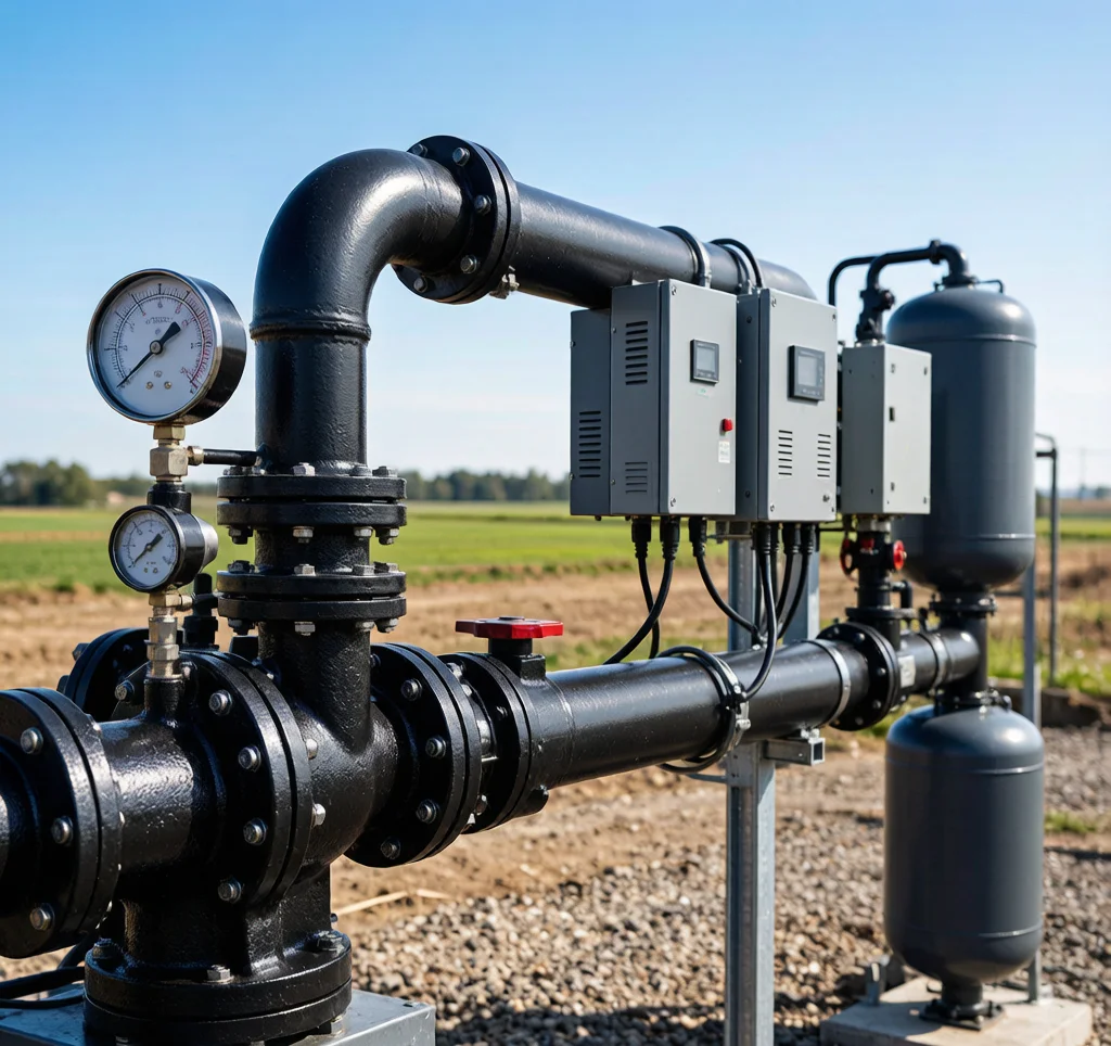
Beyond these primary devices, several complementary measures enhance overall surge resilience. Slow-closing check valves with controlled closure mechanisms prevent slam-induced pressure spikes. Soft-start variable frequency drives (VFDs) on the pump controller eliminate abrupt torque transients during startup. Vacuum breaker valves installed at pipeline high points prevent column separation and the subsequent cavity collapse that generates secondary water hammer events. For most long-distance solar pumping applications, KINBO recommends a layered protection approach combining an air vessel at the pump discharge with pressure relief valves at critical elevation points along the pipeline.
Design Considerations for Solar Pump Installations
Effective water hammer protection begins at the system design stage—not as a retrofit after commissioning. Engineers specifying solar pump systems should incorporate the following design principles to minimize surge risk from day one.
Pipe Material Selection: Different pipe materials exhibit significantly different wave propagation speeds (c), directly affecting surge pressure magnitude via the Joukowsky equation. HDPE and PE pipes, with their lower elastic modulus, produce wave speeds of approximately 250–350 m/s—roughly half that of rigid steel (1,000–1,200 m/s) or PVC (400–500 m/s). This lower wave speed translates to proportionally lower surge pressures for the same velocity change. Where project conditions permit, HDPE is often the preferred material for solar pumping discharge lines.
Velocity Control: Maintaining flow velocity below 2.0 m/s in the discharge line is a cost-effective first line of defense. The pipe diameter should be selected not only for friction loss optimization but also for surge mitigation. A useful rule of thumb: increasing pipe diameter by one nominal size typically adds 15–25% to material cost but can reduce surge pressure by 30–40% due to the combined effect of lower velocity and larger fluid mass absorbing transient energy.
Surge Analysis and Calculation: For pipelines exceeding 300 meters in length or operating with flow rates above 15 m³/h, a formal hydraulic surge analysis using software such as HAMMER, WANDA, or AFT Impulse is strongly recommended. The analysis should model worst-case scenarios including power failure during peak flow, rapid check valve closure, and pump startup against a closed discharge valve. Key outputs include maximum and minimum pressure envelopes along the pipeline, allowing engineers to verify that all components remain within their rated pressure limits under transient conditions.
Frequently Asked Questions
Can I use a simple check valve to prevent water hammer in a solar pump system?
While a check valve prevents reverse flow, a standard spring-loaded check valve can actually worsen water hammer if it closes too rapidly. The valve disc slams shut as the water column reverses, creating the exact pressure spike you are trying to avoid. The solution is to specify a slow-closing or non-slam check valve—ideally with an adjustable closure speed—and pair it with a primary surge protection device such as an air vessel or surge tank at the pump discharge.
How do I calculate the required size of a surge tank for my solar pumping pipeline?
Surge tank sizing depends on pipeline length, diameter, flow rate, static head, and allowable pressure rise. The fundamental approach calculates the volume of water that must enter the tank to decelerate the flow. A simplified formula is: Required Volume = (Pipeline Cross-Sectional Area × Pipeline Length × Initial Velocity) / (2 × g × Allowable Surge Head). However, for critical installations, a full transient hydraulic analysis is recommended. Contact the KINBO engineering support team with your system parameters for application-specific sizing guidance.
Are water hammer risks higher in solar pump systems compared to grid-powered pumps?
Yes, solar pump systems present unique water hammer challenges not found in grid-connected pumping applications. The primary differentiators are: (a) frequent start/stop cycling due to cloud-induced irradiance variations, exposing the pipeline to more transient events per day; (b) DC-powered pump motors that may decelerate differently than AC motors under load loss; and (c) the common practice of locating solar arrays away from water sources, resulting in longer-than-average pipeline runs between the pump and delivery point. These factors make surge protection even more critical in solar applications.
For B2B buyers engineering solar pump systems with long-distance pipelines, contact KINBO for competitive FOB pricing and technical specifications.