Solar Pump Surge Protection and Earthing: Field Practices to Prevent Costly Inverter Failure
Introduction
Solar pump inverters fail far more often from electrical stress than from mechanical wear. In lightning-prone and remotely earthed sites, the difference between a five-year life and a five-month life is usually grounding and surge protection. This guide covers practical solar pump surge protection and earthing field practices. KINBO builds DC-rated protection into its controllers, but correct site earthing remains the installer’s job.
Table of Contents
Why Solar Pump Inverters Fail
Long DC strings act like antennas. A nearby lightning strike induces a surge that travels down the conductors into the controller, destroying MOSFETs and the DC bus. Poor bonding also creates ground loops and differential voltages that quietly degrade components. The root cause is almost always an incomplete earthing and protection strategy, not the hardware itself.
Earthing and Grounding Design
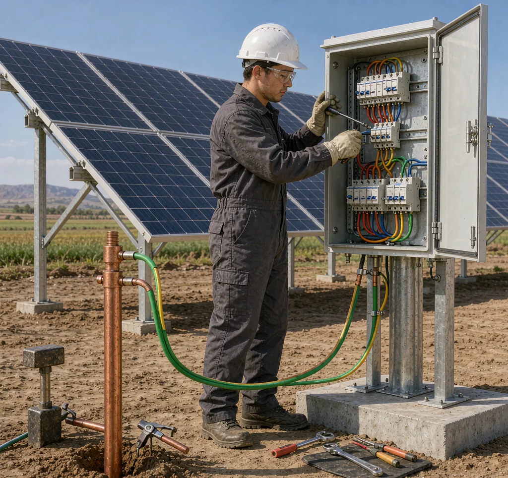
A single low-impedance earth electrode, properly bonded to every metal part, is the foundation. Panel frames, the controller enclosure, and the pump body must all sit at the same potential.
| Element | Recommended spec |
|---|---|
| Earth electrode | Copper rod >= 2 m, resistance < 10 ohm |
| Conductor | >= 6 mm2 copper, green/yellow |
| Bonding | All metal enclosures linked |
| Equipotential | Panel frames + controller + pump |
In rocky or dry soil, a single rod may not reach the target resistance. Drive two or three rods in a line and bond them, or use a ground-enhancement compound around the electrode to lower impedance. Re-test resistance seasonally, because dry-season cracking can quietly raise impedance and undo the protection the rest of the system relies on.
Surge Protection Devices
Earthing alone is not enough. Fit DC-rated surge protective devices (SPDs) at both the array entry and the controller. Use Type 1+2 combined devices rated for the array’s open-circuit voltage, with replaceable modules so a struck site can be restored quickly. Route the SPD ground lead as short and straight as possible to the electrode.
For the broader upkeep context, review our solar pump maintenance guide alongside this protection work.
When selecting an SPD, match its continuous operating voltage and Maximum Continuous Operating Voltage to the array, and confirm the clamping voltage stays below the inverter withstand rating. Modules with visible fault indicators let field staff confirm protection is still active after a storm. Protect the array entry and the controller with separate devices so a strike on the field side does not propagate into the electronics.
Installation Checklist
- Measure earth electrode resistance and confirm it is below 10 ohm.
- Bond panel frames, controller enclosure, and pump body to one electrode.
- Fit Type 1+2 DC-rated SPDs at array entry and controller.
- Keep SPD leads short; never share the protection ground with signal wiring.
- Label the electrode and record the resistance for annual inspection.
Frequently Asked Questions
Is earthing alone enough to protect the inverter?
No. Earthing manages the reference potential, but a DC-rated surge protective device is required to clamp the induced voltage spike.
What type of SPD should I use?
A Type 1+2 combined, DC-rated device matched to the array’s open-circuit voltage, with replaceable modules.
What ground resistance is acceptable?
Aim for under 10 ohms; lower is better, and supplementary rods can be added in dry or rocky soil.
How often should protection be inspected?
Annually, and after any nearby lightning strike, checking SPD status indicators and electrode resistance.
For B2B buyers deploying solar pumps in lightning-prone or remote sites, contact KINBO for competitive FOB pricing and technical specifications.
Related Articles
- Solar Pump MPPT Controller Setup and Tuning
- Solar-Powered Fish Farm Aeration: A Case Study
- Explore KINBO Built-in Controller Solar Pumps